


Lithium Battery Protection Board: Principles, Key Parameters, and Troubleshooting Guide
Introduction: Why Lithium Battery Protection Boards Matter
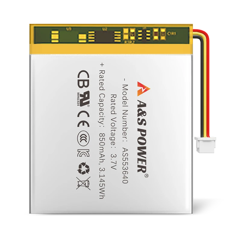
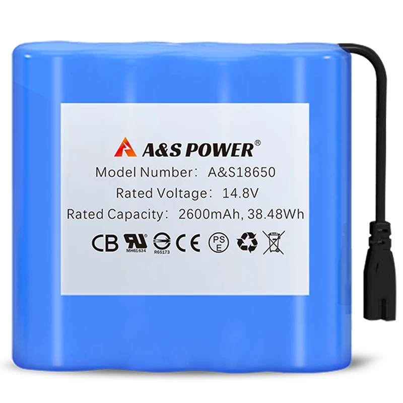
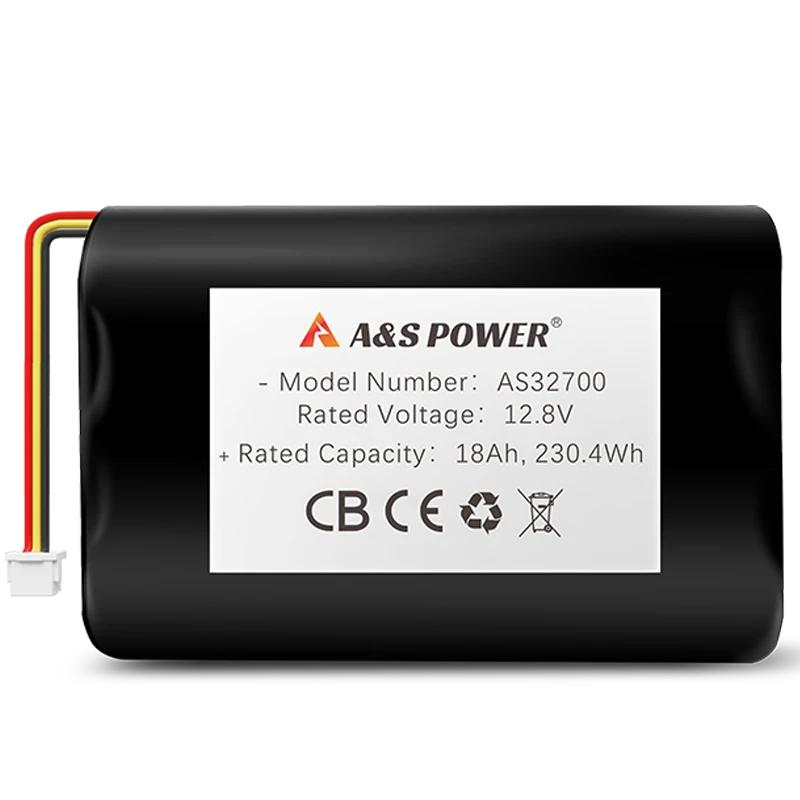
Lithium batteries—such as lithium-ion (Li-ion), lithium-polymer (LiPo), and lithium iron phosphate (LFP)—are now the power source behind consumer electronics, medical equipment, industrial devices, robotics, wearables, energy storage systems, and electric mobility. But despite their high energy density and long cycle life, lithium batteries are also highly sensitive electrochemical systems.
Without adequate protection, lithium cells can become unstable. Issues like overcharging, over-discharging, external short circuits, or high temperatures may trigger accelerated degradation, capacity fade, thermal runaway, or in worst cases, fire hazards.
This is where the lithium battery protection board—often referred to as a PCM (Protection Circuit Module) or part of a Battery Management System (BMS)—plays a crucial safety, stability, and longevity role.
This complete guide explains:
-
What a lithium battery protection board is
-
How it works
-
Core components and functions
-
Standard protection thresholds
-
Common faults and how to diagnose them
-
Repair and reset methods
-
Data-based insights for engineers, buyers, and technical decision makers
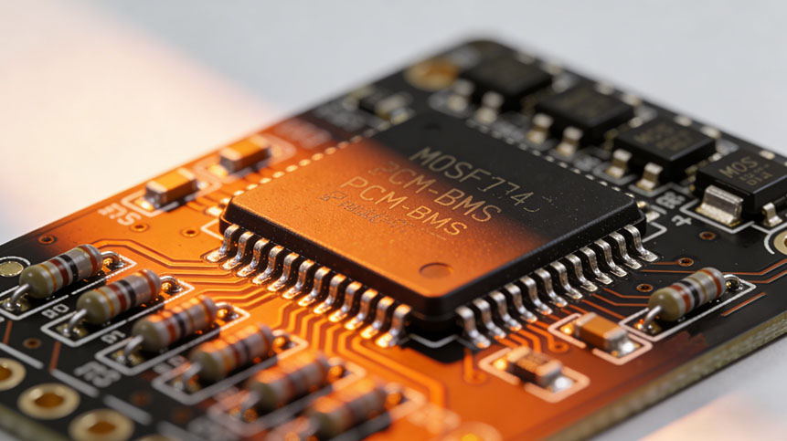
1. What Is a Lithium Battery Protection Board?
A lithium battery protection board is an electronic safety circuit built into lithium battery packs. Its primary function is to protect individual cells from electrical or thermal conditions that may cause damage or pose safety risks.
Core Functions
1.1 Charge and Discharge Protection
The protection board prevents:
-
Overcharge
-
Over-discharge
-
Over-current
-
Short circuit
-
Reverse wiring
-
Excessive temperature rise
When an abnormal condition occurs, the circuit disconnects the charging or discharging path by controlling MOSFET switches.
1.2 Cell Balancing Function
In multi-cell series packs (2S, 3S, 4S, etc.):
-
Cells charge at different speeds
-
Voltage imbalance shortens cycle life
-
The protection board enables active or passive balancing
-
It equalizes cells to maintain stable pack operation
Balancing improves:
-
Charging efficiency
-
Capacity utilization
-
Long-term durability
1.3 Real-Time Cell State Monitoring
Protection boards continuously monitor:
-
Cell voltage
-
Pack voltage
-
Charging and discharging current
-
Internal resistance
-
Temperature (via NTC or thermistors)
-
MOSFET operating status
When a parameter exceeds the safe threshold, the system activates a protective cutoff.
1.4 Auxiliary Protection Components
Some boards integrate auxiliary devices:
-
PTC (Positive Temperature Coefficient): increases resistance at high temperature
-
Fuse: provides irreversible protection
-
NTC sensor: temperature measurement for thermal shutdown
-
ID module / EEPROM: stores battery information
-
Memory components: store cycle count or protection logs
These additional elements increase reliability, especially in medical, aerospace, or industrial applications.
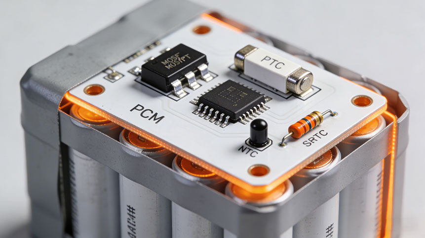
2. Key Components of a Lithium Battery Protection Board
A standard PCM includes both core electronics and auxiliaryprotective components.
2.1 Core Electronic Components
| Component | Function Description |
|---|---|
| Control IC | The brain of the protection board; monitors voltage/current/temperature. |
| MOSFETs | Switches that connect or disconnect the battery from load/charger. |
| Resistors | Voltage/current sampling, balancing circuits. |
| Capacitors | Stabilize the circuit to prevent oscillation. |
| Control logic circuits | Manage timing, thresholds, and switching sequences. |
2.2 Auxiliary Devices
| Component | Purpose |
|---|---|
| Fuse | Permanent cutoff protection against catastrophic failure. |
| PTC | Self-resetting over-temperature protection. |
| NTC | Temperature measurement to enable thermal shutdown. |
| EEPROM | Stores battery ID, cycle information, calibration values. |
| ID Chip | Authentication for smart batteries. |
These components together form the safety backbone of modern lithium battery packs.
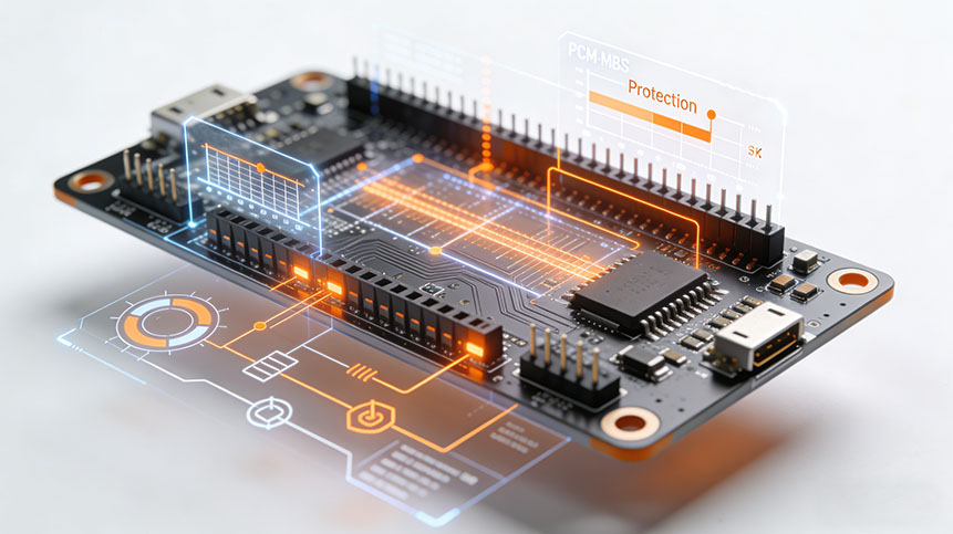
3. How a Lithium Battery Protection Board Works
The protection process depends on the coordination of control IC + MOSFETs + sensing circuits.
3.1 Environmental Adaptation
Most protection boards operate reliably from −40°C to +85°C, allowing usage in:
-
Outdoor devices
-
Automotive electronics
-
Industrial equipment
-
Consumer products
The board continuously samples:
-
Voltage (cell and total pack)
-
Current (charge/discharge)
-
Temperature
3.2 Normal Operating Mode
Under normal conditions:
-
The control IC activates MOSFET switches
-
The battery remains connected
-
Charging and discharging proceed normally
The circuit dynamically adjusts to maintain safe operation.
3.3 Abnormal Protection Mode
If any parameter exceeds the safe range, the system triggers protection.
Examples:
| Abnormal Condition | Typical Trigger Level | Protection Action |
|---|---|---|
| Overcharge | >4.25V per cell (Li-ion) | Stop charging |
| Over-discharge | <2.5–2.8V per cell | Stop discharging |
| Over-current | >10–60A depending on pack | Cut off MOSFET |
| Short circuit | Instant high current | Immediately disconnect |
| High temperature | >60°C (charging), >70°C (discharging) | Thermal shutdown |
MOSFETs disconnect the circuit within microseconds.
3.4 High-Temperature Auxiliary Mechanism
A PTC increases resistance dramatically when overheated, reducing current flow and preventing further damage.
This feature adds redundancy to the electrical cutoff.
4. Standard Voltage Protection Thresholds
Different lithium chemistries have different voltage limits. The protection board must match the cell type.
4.1 Common Voltage Protection Ranges
| Battery Chemistry | Typical Over-Charge Cutoff | Typical Over-Discharge Cutoff |
|---|---|---|
| Ternary Li-ion (NMC/NCA) | 4.20–4.25V | 2.8–3.0V |
| LFP (LiFePO4) | 3.60–3.65V | 2.5–2.8V |
| LiPo (Polymer) | 4.20V | 3.0V |
| High-voltage Li-ion | 4.35–4.40V | 2.8–3.0V |
4.2 Impact of Incorrect Thresholds
If thresholds do not match the chemistry:
-
Over-charging → gas generation, swelling, thermal runaway
-
Over-discharging → copper dissolution, permanent damage
-
Incorrect high-temp cutoff → internal short risks
Using a chemistry-matched PCM is essential for safety and cycle life.
5. Common Issues and Faults in Lithium Battery Protection Boards
This section answers the question directly — “What are the common faults of lithium battery protection boards and how do I diagnose them?”
5.1 Failure of Charge/Discharge Function
When a protection board stops charging or discharging, consider these causes:
1. Protection Triggered
The board might have entered:
-
Over-charge protection
-
Over-discharge protection
-
Over-current protection
-
Short-circuit protection
-
Temperature protection
2. MOSFET Failure
Use a multimeter to test MOSFET drain-source continuity.
3. LED Alarm
Some boards flash:
-
0.5-second intervals indicate a protection state
4. PC Software Monitoring
Smart BMS/PCM can connect to a laptop/software to view:
-
Protection logs
-
Cell voltage data
-
Error codes
5. External Switch Issue
Some PCM designs include a:
-
Low-power consumption switch
Ensure it is turned ON.
5.2 How to Diagnose a Damaged Protection Board
These simple tests determine whether the PCM is genuinely damaged.
1. Charging Test
If:
-
The charger cannot activate
-
The battery does not accept charge
-
Capacity remains zero
→ Possible protection circuit damage.
2. Output Voltage Test
If output voltage = 0V, but the cell is not dead → strong indication of PCM failure.
3. Distinguish Lockout vs. Damage
Some PCMs enter a temporary lockout due to:
-
Over-discharge
-
Short-circuit
-
Over-current events
Charging may reset the board.
6. Repair and Recovery Methods
6.1 Recovery from Protection Trigger
Over-charge, over-discharge, or short-circuit events can often be reset by:
-
Connecting a compatible charger
-
Allowing the PCM to reinitialize
6.2 Over-Current Recovery
Remove the load → PCM resets automatically.
6.3 Hardware Repair
If MOSFETs or ICs are physically damaged:
-
Replace MOSFETs
-
Replace the control IC
-
Examine solder joints and connectors
-
Inspect for burnt components under microscope
However, for commercial battery packs, replacing the PCM is often more cost-effective.
7. Data Insights: Why Protection Boards Fail
Based on industry manufacturing data (A&S Power internal manufacturing insights + public industry reports):
| Failure Cause | Occurrence Ratio | Notes |
|---|---|---|
| Over-current accidents | 32% | Often due to mismatched load |
| Over-discharge lockout | 27% | Common in devices unused for long periods |
| MOSFET thermal fatigue | 18% | Usually related to heat accumulation |
| Poor welding or connector looseness | 12% | Seen in low-cost PCM manufacturing |
| IC failure | 6% | Rare but serious |
| NTC sensor deviation | 5% | Causes false high-temperature triggers |
This data highlights why selecting a high-quality PCM manufacturer significantly impacts battery reliability.
Best Practices for Selecting a Lithium Battery Protection Board
Key Selection Checklist
-
Match chemistry (Li-ion, LiPo, LFP)
-
Confirm charge/discharge current ratings
-
Ensure correct voltage thresholds
-
Consider whether balancing is needed
-
Use UL/IEC-certified boards for medical/industrial devices
-
Evaluate MOSFET thermal performance
-
Choose a manufacturer with testing standards like:
-
UN38.3
-
IEC 62133
-
UL1642
-
UL2054
-
9. A&S Power Technical Expertise
A&S Power has manufactured lithium-ion and lithium-polymer batteries since 2010, supplying clients in:
-
Medical devices
-
Consumer electronics
-
Industrial instruments
-
Wearable devices
-
Robotics
-
GPS and mobility products
Our engineering team develops:
-
Custom BMS/PCM designs
-
Certified battery packs
-
High-precision balancing systems
-
Medical-grade battery protection circuits
10. Recommendations
Conclusion
Lithium battery protection boards are essential for ensuring the safety, reliability, and longevity of modern lithium battery packs. Understanding their working principles, voltage thresholds, common failures, and repair methods enables engineers, procurement managers, and technical teams to make informed decisions.
By applying proper diagnostics and selecting high-quality PCM/BMS components, companies can significantly reduce battery failures, product returns, and safety incidents.
A&S Power will continue contributing real engineering knowledge and reliable battery manufacturing solutions to support global partners in medical, industrial, wearable, and consumer electronics sectors.
-

 May.2026.06.10What Is a Battery Charge?Learn More
 -
 May.2026.06.10Custom Rechargeable Battery Pack: The Complete Guide for OEM ProjectsLearn More
 -
 May.2026.06.10Rechargeable Barcode Scanner Backup Battery Supplier: Complete OEM Buyers GuideLearn More
 -
 May.2026.06.10Industrial Custom Lithium Battery Pack Assembly FactoryLearn More
 -
 May.2026.06.09High Energy Density Micro Battery for Wearables OEM: The Complete Industry GuideLearn More