



Written by A&S Power Technical Team | Battery Engineering & OEM Specialists
Published: September 8, 2026 · Updated: September 8, 2026
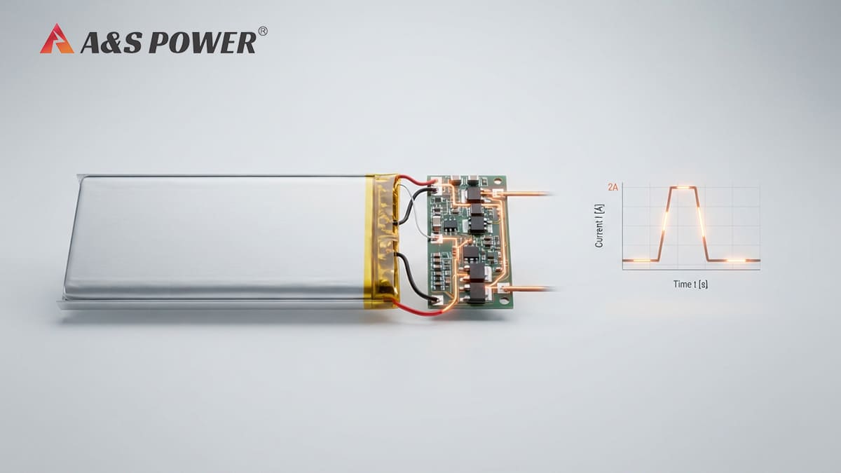
A 2A pulse rating and a PCM over-current protection threshold are not necessarily the same thing. Here is how pulse duration, protection delay, component tolerances, and real-world load conditions affect a custom LiPo battery design.
A 2.0 A pulse rating and a PCM over-current protection specification are not necessarily the same current limit.
If a custom LiPo battery is specified to support a 2.0 A pulse for up to 10 seconds, that operating condition is part of the battery's intended performance. It does not automatically mean that the PCM will disconnect the battery the instant the load reaches 2.0 A.
The actual protection behavior depends on the PCM design, protection IC characteristics, detection conditions, delay or blanking behavior, component tolerances, and the complete battery configuration. Protection IC documentation from major semiconductor manufacturers shows that over-current protection can incorporate a detection delay rather than acting as a simple instantaneous switch.
For the actual A&S Power customer case discussed in this article, the battery specification supports 2.0 A for up to 10 seconds, and A&S Power confirmed that the battery will not trip at 2.0 A for up to 10 seconds under the specified condition.
Introduction
When an OEM customer reviews a custom LiPo battery specification, one of the most common questions is what happens when the application draws a short-term peak current.
A battery may be specified to support a particular pulse current, while its PCM may also have an over-current protection specification that appears to start at approximately the same current level. At first glance, these two specifications can look contradictory.
For example, if a battery is rated for a 2.0A pulse for up to 10 seconds, but the PCM over-current protection range is listed as beginning at approximately 2.0A, an engineer may reasonably ask:
The answer is not determined by comparing the two numbers alone.
This distinction is particularly important for medical devices, handheld electronics, IoT equipment, GPS products, portable instruments, and other applications where a short peak current can be significantly higher than the normal operating current.
In this article, I will explain the difference between a LiPo battery pulse rating and PCM over-current protection, why pulse duration matters, how component tolerances should be considered, and how an OEM battery manufacturer should validate a real production battery pack.
Is a 2A Pulse the Same as a 2A PCM Protection Threshold?
No. These specifications describe different aspects of battery performance.
A battery pulse-current rating describes the current that the battery pack is designed and validated to deliver for a specified period under specified conditions.
A PCM over-current protection specification describes the conditions under which the protection circuit is designed to disconnect the load to protect the battery and the application.
Therefore, a battery that supports a 2A pulse does not automatically require the PCM to have a simple instantaneous trip point above 2A.
| Parameter | What It Describes | Why It Matters |
|---|---|---|
| Pulse Current | The current the battery pack can deliver for a specified duration. | Defines short-term load capability. |
| Continuous Current | The current the battery can provide continuously under specified conditions. | Defines normal sustained operation. |
| Over-Current Protection | The condition under which the PCM disconnects the battery from the load. | Protects the battery and system from abnormal current conditions. |
| Protection Delay | The time that an over-current condition may need to persist before protection activates. | Allows legitimate short-duration current peaks to occur without unnecessary trips. |
This is why engineers should avoid interpreting a PCM specification as though it were a simple "maximum battery current" number.
Why Doesn’t the PCM Immediately Trip at 2A?
Protection Is More Than a Single Current Number
One of the most important points in battery protection design is that an over-current protection circuit normally evaluates both current magnitude and time.
The protection IC measures current through the sensing path and determines whether the detected condition satisfies its over-current protection criteria. Depending on the protection architecture, the circuit can include a detection threshold and a time delay or blanking period before the MOSFETs are switched off.
This means that a short current peak does not necessarily produce the same response as a sustained over-current condition.
For example, protection ICs used in lithium-ion and lithium-polymer battery systems can include configurable or specified delays for over-current and overload detection. This type of behavior is one reason why the nominal current value alone should not be interpreted as an instantaneous trip point.
Current threshold + detection time + actual load profile are more meaningful than a single current number when evaluating whether a PCM will trip.
Why Does Pulse Duration Matter?
Pulse duration is critical because the protection circuit needs to distinguish between a legitimate short-term load demand and a potentially abnormal over-current condition.
Consider two different loads:
- 2.0A for a very short pulse
- 2.0A continuously for an extended period
These two operating conditions may have completely different effects on the battery and protection circuit.
A short pulse may be within the intended operating envelope, while a sustained current at the same level may create additional heating or meet the conditions required for protection.
This is why OEM battery specifications should define pulse current together with pulse duration.
In many applications, the real requirement is not simply:
Instead, the real requirement may be:
Those two descriptions represent very different battery-design requirements.
A Real A&S Power OEM Case: 2A for 10 Seconds
A practical OEM battery project helps illustrate the difference more clearly.
In this case, the customer reviewed the battery specification and raised the following concern:
The important point is that A&S Power confirmed the specified operating condition: 2.0A pulse current for up to 10 seconds will not trip the PCM under the specified battery condition.
This does not mean that every PCM labeled with a 2.0A protection specification will behave identically. It means that for this particular battery design and specified operating condition, the pack was designed to support the required pulse without triggering over-current protection.
Do not compare the battery pulse rating and PCM protection number as if they were identical specifications. The correct question is whether the complete battery pack has been designed and validated for the required current-time profile.
What About PCM Component Tolerances?
Component tolerance is an important concern when an OEM customer asks for a guaranteed production threshold.
A battery protection circuit is made from multiple components, including the protection IC, current-sensing path, MOSFETs, resistors, PCB traces, connectors, and other electrical elements. Each component can have manufacturing tolerances and temperature-dependent characteristics.
Therefore, an engineering specification should not assume that a nominal value represents an exact fixed production value for every battery pack.
The actual protection behavior can be affected by factors such as:
- Protection IC characteristics and tolerance
- Current-sensing resistance and tolerance
- MOSFET electrical characteristics
- PCB resistance and layout
- Battery voltage
- Operating temperature
- Load characteristics
- Pulse duration
- Pulse frequency and repetition
- Production variation
For this reason, if an OEM customer specifically requires a guaranteed production threshold, the battery manufacturer should define and validate the relevant production specification rather than simply interpreting a nominal PCM value.
In the A&S Power case discussed here, the confirmed requirement is that the specified 2.0A / 10-second pulse condition does not trip the PCM. A specific guaranteed numerical threshold above 2.0A should only be stated when it has been formally defined and validated as a production requirement.
Why OEM Battery Design Should Start With the Load Profile
One of the most effective ways to avoid confusion between battery current ratings and PCM protection is to start with the application's actual load profile.
When we evaluate a custom LiPo battery for an OEM application, the current requirement should ideally include more than one number.
| Load Parameter | Example Requirement | Why It Matters |
|---|---|---|
| Normal Operating Current | 0.5A | Defines typical battery load. |
| Peak / Pulse Current | 2.0A | Defines the maximum short-term demand. |
| Pulse Duration | Up to 10 seconds | Determines how long the battery must support the peak. |
| Pulse Frequency | Application dependent | Repeated pulses can produce additional heating and stress. |
| Rest Interval | Application dependent | Determines thermal recovery between pulses. |
| Minimum Battery Voltage | Application dependent | Electrical behavior can change as the battery discharges. |
| Operating Temperature | Application dependent | Temperature can affect battery and protection performance. |
Providing this information to the battery manufacturer allows the battery, PCM, cell, connector, and other components to be evaluated as a complete system.
2A Pulse Current Does Not Mean 2A Continuous Current
Another common misunderstanding is treating the pulse-current rating as though it were the battery's continuous current capability.
These are different specifications.
A battery can be designed to provide a higher current for a limited period while having a lower continuous operating current.
For example, an application might have:
- Normal operating current: 0.4–0.6A
- Peak current: 2.0A
- Peak duration: up to 10 seconds
- Long-term average current: significantly below 2.0A
In such a case, designing the battery only around the 2.0A number without considering the time profile could result in an unnecessarily conservative or incorrectly configured battery system.
Conversely, if an application actually draws 2.0A continuously, the battery and PCM need to be evaluated under that continuous load rather than relying on a 10-second pulse specification.
How Should OEM Customers Validate a 2A Pulse?
The most reliable approach is to test the complete production-intent battery pack under the actual application load profile.
For a 2.0A pulse lasting up to 10 seconds, a practical validation process can include the following steps:
- Define the complete load profile. Record the normal current, peak current, pulse duration, pulse repetition, and rest interval.
- Confirm the battery specification. Verify that the cell and battery pack are designed for the required current and duration.
- Confirm the PCM configuration. Review the protection IC, current-sensing configuration, MOSFETs, and relevant protection specifications.
- Test the actual battery pack. Use a production-intent PCM and battery configuration rather than evaluating only individual components.
- Repeat the test under relevant conditions. If required by the application, evaluate different battery voltages and operating temperatures.
- Monitor for unintended protection. Verify that the PCM does not disconnect during the specified legitimate pulse.
- Check recovery behavior. Confirm that the battery remains stable after the pulse and returns to normal operation.
This type of validation is more meaningful than simply asking whether "2A is above or below the PCM threshold."
What Should You Ask Your Custom Battery Manufacturer?
What Is the Specified Pulse Current?
Ask the manufacturer to clearly define the maximum pulse current and the corresponding duration. "Peak current" without a time specification is incomplete.
Will the PCM Trip During the Specified Pulse?
This is often more useful than comparing the pulse current directly with a nominal protection number. The manufacturer should confirm whether the complete battery pack supports the specified load profile without unintended protection.
Has the Actual Battery Pack Been Validated?
A battery pack should ideally be evaluated as a complete assembly. Cell capability, PCM behavior, MOSFET resistance, connector resistance, wiring, and PCB design can all influence real-world performance.
Are Component Tolerances Considered?
If the application has a narrow operating margin, ask how production variation and component tolerances are handled.
Does Temperature Affect the Requirement?
If the device will operate in a wide temperature range, the battery manufacturer should know the required operating temperature range so the design can be evaluated accordingly.
How A&S Power Approaches This Type of Requirement
At A&S Power, we treat custom battery requirements as application-specific engineering requirements rather than simply selecting a cell based on voltage and capacity.
For an OEM project involving a high peak current, we consider the complete battery configuration, including:
- Battery cell chemistry and electrical characteristics
- Nominal voltage and capacity
- Continuous operating current
- Peak and pulse current
- Pulse duration
- PCM protection requirements
- Protection IC configuration
- MOSFET selection
- Current-sensing configuration
- Connector and wire requirements
- Battery dimensions and mechanical constraints
- Operating temperature
- Required certifications and compliance
The 2.0A / 10-second case demonstrates why the battery specification and PCM protection specification need to be interpreted together.
The goal is not simply to make the PCM protection threshold as high as possible. Excessively increasing protection limits can reduce the protection margin of the battery. Instead, the objective is to establish an appropriate operating window in which the legitimate application load can operate normally while abnormal current conditions can still be protected.
The right PCM configuration is the one that protects the battery while allowing the real application load profile to operate reliably.
Key Takeaways
- A 2A battery pulse rating is not the same thing as a 2A PCM over-current trip threshold.
- PCM protection behavior can depend on both current magnitude and time.
- A short 2.0A pulse can be a supported operating condition even when a PCM specification appears to begin around 2.0A.
- In the A&S Power OEM case, the specified 2.0A pulse for up to 10 seconds was confirmed not to trip the PCM.
- Component tolerances should be considered when an OEM customer requires a guaranteed production-level protection specification.
- Battery requirements should define the complete current-time load profile, not just a peak current number.
- The actual production-intent battery pack should be validated under the application's real operating conditions.
- A custom PCM should balance two goals: preventing nuisance trips while maintaining appropriate battery protection.
Conclusion
The apparent conflict between a 2.0A LiPo battery pulse rating and a PCM over-current protection range beginning around 2.0A can be resolved by understanding that these are not equivalent specifications.
The battery pulse rating describes what the battery pack is designed to deliver for a defined period. The PCM protection specification describes when the protection circuit is intended to disconnect the battery under an over-current condition.
Because protection behavior can depend on current magnitude, duration, detection characteristics, component tolerances, temperature, and the complete electrical design, the correct way to evaluate a 2A pulse is to consider the entire load profile and validate the complete battery pack.
In the A&S Power OEM case, the required condition was clearly defined: 2.0A pulse current for up to 10 seconds. A&S Power confirmed that the PCM will not trip during this specified pulse condition.
For OEM customers, this is the key lesson: if your application has a peak-current requirement, provide the battery manufacturer with the actual current, duration, repetition, temperature, voltage, and operating conditions. These details allow the battery supplier to design and validate the cell and PCM together rather than relying on a single nominal current number.
Need a Custom LiPo Battery That Can Handle Your Peak Current?
If your device requires a specific peak or pulse current, A&S Power can help evaluate the battery cell, PCM, protection requirements, dimensions, connector, and application load profile for your OEM battery project.
When contacting us, please provide your required voltage, capacity, continuous current, peak current, pulse duration, pulse frequency, battery dimensions, connector requirements, and operating temperature whenever available.
Request a Custom Battery QuoteFrequently Asked Questions
1. Why doesn't a 2A LiPo battery pulse immediately trip the PCM?
A PCM does not necessarily operate as an instantaneous switch at one exact current value. Over-current protection can involve a current detection threshold and a specified detection or delay period. Therefore, the actual current-time profile needs to be considered.
2. Can a LiPo battery support 2A for 10 seconds?
It depends on the specific battery design and specification. In the A&S Power OEM case discussed in this article, the battery specification supports a 2.0A pulse for up to 10 seconds, and A&S Power confirmed that the PCM will not trip during the specified pulse condition.
3. Is the PCM over-current threshold the maximum current of the battery?
No. The PCM over-current protection specification should not automatically be interpreted as the maximum allowable operating current of the battery. The protection circuit is designed to respond to abnormal current conditions according to its electrical and timing characteristics.
4. Why is pulse duration important for PCM protection?
Pulse duration determines how long the over-current condition exists. A short peak and a sustained current can produce different protection behavior. This is why a battery pulse specification should always include the duration of the pulse.
5. Do PCM component tolerances affect the actual protection behavior?
Yes. Protection IC characteristics, sensing components, MOSFETs, PCB resistance, temperature, and production variation can influence the actual behavior of a battery protection circuit. If a project requires a guaranteed production-level threshold, the requirement should be formally defined and validated.
6. What information should I provide to a custom battery manufacturer?
Ideally, provide nominal voltage, capacity, continuous current, peak current, pulse duration, pulse frequency, rest interval, minimum operating voltage, operating temperature, battery dimensions, connector requirements, and any required certifications.
7. Can A&S Power customize a LiPo battery for a specific peak-current requirement?
Yes. A&S Power provides custom LiPo battery and OEM battery pack solutions. The battery configuration can be evaluated according to the required voltage, capacity, current profile, dimensions, PCM protection, connector, and application requirements.
Recommended External References
- Texas Instruments BQ29311 Battery Protection IC Datasheet — Technical reference for battery protection functions and over-current detection behavior.
- Texas Instruments BQ29311 Product Information — Manufacturer information for a lithium-ion battery protection IC.
- Texas Instruments BQ24316 — Battery over-current and protection reference information.
- Texas Instruments TIDA-00265 — Reference design for single-cell Li-ion / Li-polymer battery protection.