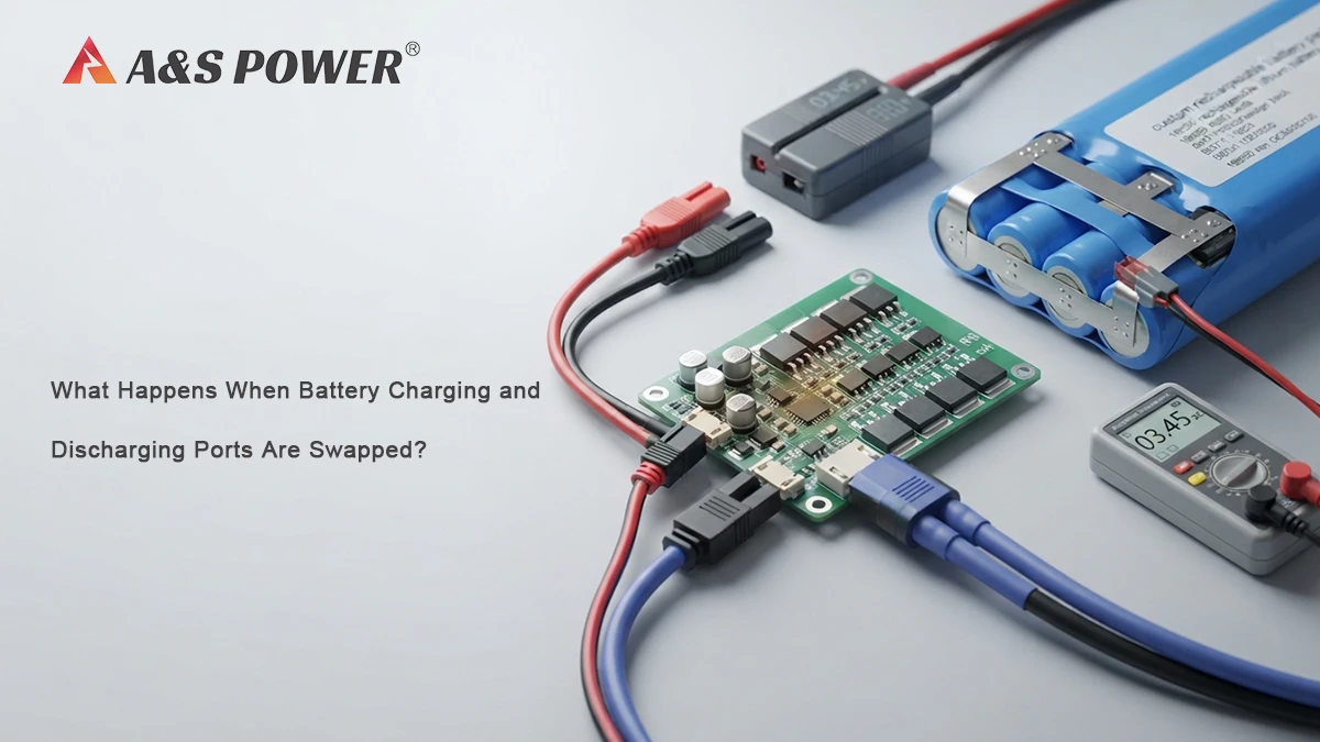





Quick Answer
When a battery's charging and discharging ports are accidentally swapped, the result depends on how the protection circuit is designed and how the BMS responds to the incorrect connection.
In our experience at A&S Power, there are typically two possible outcomes:
- Protection Activated: The BMS cuts off the circuit and prevents normal charging. Once the battery is connected correctly through the proper port, it can return to normal operation, assuming no component damage has occurred.
- MOSFET Failure: The protection MOSFET is damaged or shorted. In this condition, the BMS may lose its ability to control the battery's discharge path. The battery can then continue supplying power without normal over-discharge protection, creating a risk of deep cell discharge.
In one real customer case, the battery continued to show approximately 5 V at the discharge port after being charged correctly, while the cells had subsequently been found at approximately 1.5 V. Based on these symptoms, A&S Power identified a shorted protection MOSFET as the likely failure mode. Because the battery had lost its normal protection function, we recommended discontinuing its use.
Key Takeaways
- Charging and discharging ports are not necessarily interchangeable on a battery with separate ports.
- A correctly designed BMS may respond to an incorrect connection by activating protection.
- In some failure conditions, the protection MOSFET can become shorted or damaged.
- A damaged MOSFET can prevent the BMS from providing normal discharge protection.
- A display or electronic load continuing to work does not prove that the BMS is functioning correctly.
- A cell voltage of around 1.5 V indicates severe over-discharge for a typical lithium-ion or LiPo cell and should be treated as a serious battery failure condition.
- If the protection circuit is confirmed to be damaged, the battery should not continue in normal service.
Introduction
Separate charging and discharging ports are used in many custom battery packs because the battery system may have different requirements for charging, load output, protection, or system integration.
However, this configuration also creates an important engineering question:
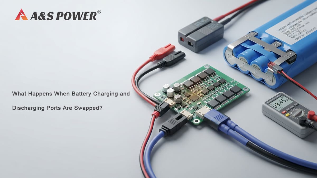
What happens if the charging and discharging ports are accidentally swapped?
This question came directly from a real customer application that we investigated at A&S Power.
The customer found that the charging and discharging connections had been swapped during system integration. Interestingly, the problem was not immediately obvious because the charging port could provide approximately 1 A, and the customer's display functioned normally.
Later, however, the batteries were found to have been discharged to approximately 1.5 V at the cell level. The reported voltage at the discharge port was around 5 V.
The customer wanted to understand why the BMS had not prevented this condition.
From a battery engineering perspective, this is an important example because it shows that normal-looking system behavior does not always mean that the battery protection circuit is operating normally.
1. Understanding Separate Charging and Discharging Ports
A battery pack can be designed with a common charge/discharge port or with separate ports.
With a common-port design, charging and discharging typically share the same external electrical path, with the protection circuit controlling the current flow.
With a separate-port design, the charging path and discharge path are electrically managed according to the battery protection architecture.
The exact circuit depends on the battery design, cell configuration, protection IC, MOSFET arrangement, wiring, and application requirements.
For this reason, the charging port should not automatically be treated as interchangeable with the discharge port.
When the wrong port is connected, the current can flow through a path that the protection circuit was not intended to handle under that operating condition.
This is why correct identification of CHARGE+ / CHARGE− and DISCHARGE+ / DISCHARGE− is important during system integration and production testing.
2. How Does the BMS Normally Protect the Battery?
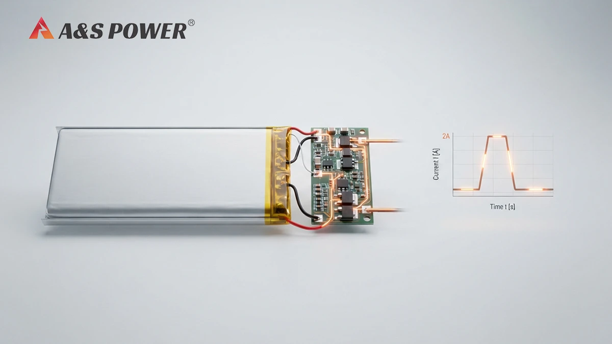
A Battery Management System (BMS), or a protection circuit in smaller battery packs, monitors important battery conditions and controls the electrical path through switching devices such as MOSFETs.
Depending on the design, protection functions can include:
- Overcharge protection
- Over-discharge protection
- Over-current protection
- Short-circuit protection
- Abnormal charging protection
- Cell voltage monitoring
- Temperature protection
The MOSFETs are particularly important because they act as electronic switches in the battery current path.
Under normal conditions, the protection IC determines whether the MOSFETs should remain on or turn off.
For example, if the battery reaches an over-discharge condition, the protection circuit can turn off the relevant MOSFET and disconnect the load from the cell.
This prevents the cell from continuing to discharge below the specified protection threshold.
However, the protection function only works if the protection circuit and its switching components remain electrically healthy.
This distinction is critical in the customer case we investigated.
3. What Happens When the Charging and Discharging Ports Are Swapped?
Based on our engineering analysis, there are typically two possible outcomes when separate charging and discharging ports are swapped.
3.1 Scenario 1: The BMS Activates Protection
The first possibility is that the protection circuit recognizes the abnormal electrical condition and activates protection.
In this situation, the BMS cuts off the relevant circuit and prevents normal charging or current flow through the incorrect path.
The battery may appear to be inactive or unable to charge.
Once the battery is connected correctly through the intended charging port, the protection circuit may recover and the battery can return to normal operation, assuming no component damage has occurred.
This is the preferable outcome because the protection circuit has responded as intended.
However, the exact behavior depends on the specific BMS topology and electrical design.
3.2 Scenario 2: The Protection MOSFET Is Damaged
The second possibility is more serious.
Under an abnormal connection, the protection MOSFET may be exposed to an electrical condition outside its intended operating range. If the MOSFET is damaged and becomes shorted, the protection circuit may no longer be able to disconnect the battery from the load.
In this condition, the BMS protection IC may still exist physically on the PCB, but the battery can effectively lose its normal protection function because the switching element that should interrupt the current path is no longer operating correctly.
This is an important distinction:
A damaged BMS does not necessarily mean that the PCB is completely electrically dead.
The battery may still produce an output voltage and may even power the customer's electronics.
But the protection function can be compromised.
4. Why Did the Display Still Work?
This was one of the most important clues in the customer's case.
The incorrect connection did not immediately appear to cause a complete system failure.
The charging port could provide approximately 1 A, and the customer's display functioned normally.
At first glance, this could make the battery appear healthy.
But the display operating normally only tells us that some electrical power was reaching the system.
It does not confirm that:
- The BMS over-discharge protection is functional.
- The protection MOSFET can switch off correctly.
- The battery can safely disconnect from the load.
- The cells are protected against excessive discharge.
This is why functional testing of the end product alone may not be enough to verify battery protection.
A display can continue operating while the battery protection system has already suffered damage.
5. How Can a Damaged BMS Lead to 1.5 V Over-Discharge?
Under normal operation, the BMS should prevent the battery cell from continuing to discharge after the cell reaches its defined protection threshold.
If the discharge MOSFET is functioning correctly, the protection circuit can interrupt the load current.
But if the MOSFET has been shorted or otherwise damaged, the protection circuit may lose control over the discharge path.
The electronic device can then continue drawing current from the battery.
As the load continues operating, the cell voltage gradually decreases.
Eventually, the cell can reach a severely over-discharged condition.
In the customer's case, the cells were found at approximately 1.5 V.
For a typical lithium-ion or LiPo cell designed around a nominal voltage of approximately 3.6–3.7 V, 1.5 V represents a severe discharge condition and is far outside normal operating voltage.
At this point, the issue is no longer simply that the battery has "low voltage."
It indicates that the cell may have experienced significant over-discharge and requires appropriate engineering evaluation rather than being returned directly to normal service.
6. Why Was the Battery Still Around 5 V at the Discharge Port?
Another important observation from this case was that the reported discharge-port voltage was approximately 5 V, even after the battery was charged correctly.
This behavior helped our engineering team distinguish between the two possible scenarios.
If the protection circuit had simply entered a normal protection state, reconnecting the battery through the correct charging path could potentially restore normal operation.
However, in this case, the battery continued to provide an output around 5 V through the discharge port.
Combined with the later discovery that the cells had been deeply over-discharged, this behavior was consistent with the second failure mode identified by A&S Power:
The protection MOSFET had likely been shorted, leaving the battery without normal discharge protection.
The important point is that the 5 V output by itself should not be used as the sole diagnostic criterion. It needs to be evaluated together with the battery's internal cell voltage, protection behavior, charging behavior, and the condition of the protection circuit.
7. How to Diagnose a Suspected BMS or MOSFET Failure
When a battery has experienced an incorrect charge/discharge connection, we recommend avoiding assumptions based only on the output voltage.
A more systematic investigation should include the following checks.
Identify:
- Cell chemistry
- Series/parallel configuration
- Nominal voltage
- Full-charge voltage
- Discharge-port voltage
- Charging-port voltage
- Protection architecture
- Charging and discharge current requirements
Measure the actual cell voltage rather than relying only on the external battery output.
This can help determine whether the cells are normally charged, deeply discharged, or unbalanced.
The engineering team should determine whether the battery protection circuit can still disconnect the load under the appropriate protection conditions.
If the protection circuit is suspected of failure, the MOSFET should be evaluated for abnormal resistance or short-circuit behavior.
The measured behavior should be compared with the battery's approved electrical specification and BMS protection design.
This is particularly important for custom OEM batteries because the protection parameters are application-specific.
8. Why You Should Stop Using a Battery With Lost Protection
A lithium battery with a confirmed damaged protection circuit should not be treated as a normal battery simply because it can still produce voltage.
The purpose of the BMS or protection circuit is not only to make the battery work.
Its more important role is to prevent the battery from operating outside defined electrical limits.
If the protection MOSFET has failed and the battery can no longer disconnect the load during an over-discharge event, the normal safety architecture has been compromised.
In the customer case described here, A&S Power therefore recommended discontinuing use of the affected battery.
The battery should be isolated and evaluated according to the manufacturer's safety and quality procedures rather than returned directly to the product.
9. How OEM Battery Design Can Reduce This Risk
For custom battery projects, preventing port-mismatch problems starts before mass production.
At A&S Power, we recommend that customers define the following requirements during battery development:
Clearly Define Charge and Discharge Ports
The connector and wiring should clearly distinguish charging and load connections.
Review the Protection Architecture
The BMS design should be reviewed according to:
- Maximum charging current
- Continuous discharge current
- Pulse discharge current
- Over-current protection
- Short-circuit protection
- Over-charge protection
- Over-discharge protection
- Temperature requirements
Test Abnormal Connection Conditions
Where the application creates a realistic possibility of incorrect connection, the battery/system interface should be evaluated for foreseeable misuse and abnormal conditions.
Test the Complete System
Battery protection should not be validated only at the battery level.
The battery, charger, display, controller, connector, wiring, and final load should be evaluated together because the actual failure mode can depend on the complete electrical system.
10. What This Real Customer Case Teaches Us
This case illustrates an important principle in battery engineering:
A battery that still powers the product is not necessarily a battery that is still protected.
The customer initially saw normal display operation and approximately 1 A charging capability, so the port mismatch did not immediately look serious.
The later discovery of approximately 1.5 V cell voltage changed the situation completely.
The combination of:
- Swapped charging and discharging ports,
- Continued system operation,
- Approximately 5 V output at the discharge port,
- Deep cell over-discharge to approximately 1.5 V,
led A&S Power to identify a likely protection MOSFET short and loss of normal BMS discharge protection.
This is why battery troubleshooting should consider both battery performance and protection behavior.
Key Takeaways
- The BMS may activate protection and prevent abnormal charging.
- In a more serious failure, the protection MOSFET may become damaged or shorted.
- A shorted MOSFET can prevent the BMS from properly disconnecting the load.
- The battery may continue powering the product even though its protection function has been compromised.
- Continued discharge can drive the cells into severe over-discharge.
- A cell voltage around 1.5 V should be treated as a serious abnormal condition for a typical 3.6–3.7 V Li-ion/LiPo cell.
- A battery with confirmed protection-circuit damage should be removed from normal service.
- For custom battery projects, charge/discharge port design and abnormal-condition testing should be considered during the engineering stage.
Conclusion
Swapping the charging and discharging ports of a battery pack can create a problem that is not immediately visible at the system level.
In the real customer case discussed by A&S Power, the display continued to function and the charging path could provide approximately 1 A, but the battery subsequently experienced severe cell over-discharge to approximately 1.5 V.
Our engineering analysis identified two possible BMS responses: normal protection activation or protection MOSFET failure. Based on the combination of continued discharge-port output and severe over-discharge, the second condition was considered the likely explanation—the protection MOSFET had been shorted and the battery had lost its normal discharge protection.
The key lesson is simple:
Do not judge battery protection by output voltage or product operation alone.
For OEM battery applications, the charging path, discharge path, BMS architecture, MOSFET protection, system load, and abnormal connection conditions should all be considered together.
If a battery has experienced an incorrect port connection and subsequently shows abnormal voltage or over-discharge behavior, it should be evaluated by the battery manufacturer before being returned to service.
Frequently Asked Questions
Can I use the charging port as the discharge port?
Not unless the battery manufacturer specifically confirms that the battery is designed for this configuration. Separate charging and discharging ports can have different electrical paths and protection behavior.
What happens if the charge and discharge ports are connected incorrectly?
The BMS may activate protection and prevent normal operation. In a more serious case, a protection MOSFET can be damaged, potentially causing the battery to lose normal discharge protection.
Can a battery still work if its BMS is damaged?
Yes. A damaged protection circuit does not necessarily mean that the battery produces zero voltage. The battery may continue powering an electronic device while some or all protection functions have been compromised.
Why did the display continue working after the port was swapped?
The display only indicates that electrical power was still available to the system. It does not prove that the battery's BMS and protection MOSFET were functioning correctly.
Is 1.5 V too low for a LiPo battery?
For a typical single Li-ion or LiPo cell with a nominal voltage around 3.6–3.7 V, 1.5 V is a severe over-discharge condition. The battery should not simply be returned to normal use without appropriate evaluation.
Can a shorted MOSFET cause battery over-discharge?
Yes. If the MOSFET responsible for disconnecting the load is shorted or otherwise unable to switch off, the protection circuit may lose its ability to interrupt discharge. Continued load current can then cause severe cell over-discharge.
Should I continue using a battery after a suspected BMS failure?
No. If the protection circuit or MOSFET has been confirmed or strongly suspected to be damaged, the battery should be removed from normal service and evaluated according to the manufacturer's safety procedures.
How can an OEM battery manufacturer prevent this problem?
The battery design should clearly define charging and discharging ports, specify the BMS protection architecture, select suitable MOSFETs and protection parameters, and evaluate foreseeable abnormal connection conditions during battery and system testing.
About A&S Power
At A&S Power, we approach custom battery development from both the cell and system perspectives. Through our cooperation with OEM customers, we regularly research practical questions that arise during product development, integration, testing, and mass production.
Real customer engineering questions—such as incorrect charge/discharge connections, BMS protection behavior, MOSFET failure, and unexpected battery voltage—help us understand the problems battery engineers and product developers encounter in actual applications.
For custom Li-ion, LiPo, and LiFePO4 battery projects, our engineering team can work with customers on battery specifications, protection circuits, connectors, charging requirements, discharge characteristics, and application-specific battery design.
Need Help With a Custom Battery?
If your product requires a custom rechargeable battery with separate charging and discharging ports, the protection architecture should be considered from the beginning of the project—not only after an abnormal condition occurs.
Contact A&S Power to discuss your battery requirements, protection design, connector configuration, and OEM/ODM production needs.
Get Custom Battery Quote